


 Category Index


AutoLISP Function to Generate a Table of Selected Polyline Data
Creates a table containing the vertex coordinates, segment lengths (intermediate distances), area, and perimeter of the selected Polyline objects.
admin - 23.05.2026 08:35
admin - 23.05.2026 08:35
AutoLISP Function to Generate a Table of Selected Polyline Data
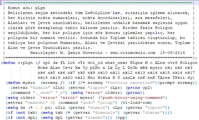
Creates a table containing the vertex coordinates, segment lengths (intermediate distances), area, and perimeter of the selected Polyline objects.
Command Name: pLgn
RAR Password: www.cizimokulu.com
Previously shared on the autodacdokulu.com forums, this function has been revised and enhanced based on requests from our users and is now being reintroduced.
The source code is provided in open format so that fellow developers can review and follow the implementation details.
Extract the pLgn.lsp file from the archive into the AutoCAD Support folder, then load it either using APPLOAD or from the AutoCAD Command Line with:
(load "pLgn.lsp")
For proper operation, the user must have sufficient access permissions to the AutoCAD folders.
All LwPolyline objects within the selected selection set are processed sequentially as follows:
If multiple polygons are selected, each polygon is assigned a unique number and labeled at its geometric center.
If only one polygon is selected, no polygon numbering is applied.
For each polygon:
Vertex points are numbered sequentially starting from 1.
These point numbers are displayed both on the polygon and within the generated table, allowing direct correlation between the coordinate data and the graphical points.
For every polygon, the following data are calculated and written into a table using the specified decimal precision:
Polygon vertex coordinates are calculated and displayed in the current UCS.
When multiple polygons are selected:
After selection is completed, the drawing automatically zooms to an appropriate view and allows the completed table to be dragged and placed at the desired location.
Each polygon is displayed individually with an appropriate zoom level, and the user is prompted to specify the placement point of the corresponding table.
The function is completed after displaying and placing the final Polygon Summary Table.
If only a single Polyline is selected:
No Polygon Summary Table is created.
No polygon number is assigned.
Good luck.
Updates:
The error handling routine has been redesigned and improved.
Support for standard Polyline objects has been added alongside LwPolyline (processed using XY-plane projection for 3D Polyline objects).
Since the function generates its own DCL file, sufficient permissions for AutoCAD folders are required, or AutoCAD should be run as Administrator.
To minimize previous loading and execution issues, the archive now also includes the PLgn.vlx version.
Creates a table containing the vertex coordinates, segment lengths (intermediate distances), area, and perimeter of the selected Polyline objects.
Command Name: pLgn
RAR Password: www.cizimokulu.com
Previously shared on the autodacdokulu.com forums, this function has been revised and enhanced based on requests from our users and is now being reintroduced.
The source code is provided in open format so that fellow developers can review and follow the implementation details.
Extract the pLgn.lsp file from the archive into the AutoCAD Support folder, then load it either using APPLOAD or from the AutoCAD Command Line with:
(load "pLgn.lsp")
For proper operation, the user must have sufficient access permissions to the AutoCAD folders.
All LwPolyline objects within the selected selection set are processed sequentially as follows:
If multiple polygons are selected, each polygon is assigned a unique number and labeled at its geometric center.
If only one polygon is selected, no polygon numbering is applied.
For each polygon:
Vertex points are numbered sequentially starting from 1.
These point numbers are displayed both on the polygon and within the generated table, allowing direct correlation between the coordinate data and the graphical points.
For every polygon, the following data are calculated and written into a table using the specified decimal precision:
Point numbers
Vertex coordinates
Segment distances
Area
Perimeter
Polygon vertex coordinates are calculated and displayed in the current UCS.
When multiple polygons are selected:
The complete process is repeated for each polygon.
Each polygon receives an identification number.
After processing all polygons, a Polygon Summary Table is generated showing:
Polygon Number
Area
Perimeter
Total Area
Total Perimeter Length
After selection is completed, the drawing automatically zooms to an appropriate view and allows the completed table to be dragged and placed at the desired location.
Each polygon is displayed individually with an appropriate zoom level, and the user is prompted to specify the placement point of the corresponding table.
The function is completed after displaying and placing the final Polygon Summary Table.
If only a single Polyline is selected:
No Polygon Summary Table is created.
No polygon number is assigned.
Good luck.
Updates:
The error handling routine has been redesigned and improved.
Support for standard Polyline objects has been added alongside LwPolyline (processed using XY-plane projection for 3D Polyline objects).
Since the function generates its own DCL file, sufficient permissions for AutoCAD folders are required, or AutoCAD should be run as Administrator.
To minimize previous loading and execution issues, the archive now also includes the PLgn.vlx version.
Author: cizimokulu.com
Description: AutoLISP Function to Generate a Table of Selected Polyline Data
Tag:
Comments :
No comment yet